LED Flowerpot
April 10th 2008The LED Flowerpot!
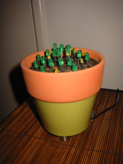
This is a little project I built as a gift for the Wife for the combined 5-year being together anniversary/Valentine’s Day. I did most of the work on the weekends, soldering and gluing in the back yard out of sight from prying wifey eyes.
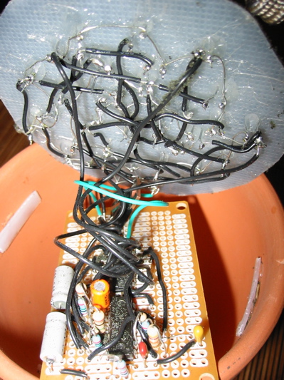
The circuit is not terribly complicated, it’s a modified version of Wilf Rigter’s Quad LED Fader circuit (specifically QLF6) I found on the BEAM robotics community server. It uses a 74C14 Schmitt triggered inverter chip as a bank of five oscillators fed into a LM339 quad comparator to generate four slow wave forms to drive four banks of LEDs. The 74C14 was provided by my good friend and chip dealer, Mr. Bunt. The major addition I made to the circuit was a voltage regulator to change its power supply to use a wall wart scavenged from a defunct answering machine that I haven’t seen in years. A 9-volt battery, its package being the ideal size to fit in the flowerpot base, unfortunately drained quickly with the number of LEDs I wanted to use.
Soldering the circuit itself onto the prototype board wasn’t much of a chore but as you can see, I do needs me some practice at circuit layout. The most irritating thing was wiring up all the LEDs. There’s 34 of the little buggers and each one had to be hot glued in and wired up to their brethren and the circuit. The result of which is the rat’s nest you see before you. I only have black wire, OK?
The prototype board rests on the sides of the pot, stuffed down below the “dirt’s” surface. The surface itself is made from a round cut from a cheap cutting board that was too crappy to actually use as a cutting board. Scraps left over from the same were hot glued to the sides of the pot to hold the surface at the desired depth.
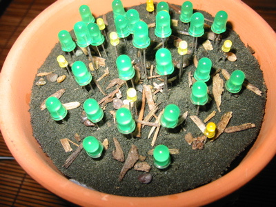
The LEDs were hotglued into position before being wired up for action. First I had to make holes in the cutting board round to stuff the LEDs through. I originally intended to use a drill to create the holes, but quickly found that my smallest drill bit opened cavernous orifices compared to the width of the leads on your average LED. In the end I used a needle heated with a lighter to pierce the holes. Not only was the pierced diameter perfectly suited for LED leads, I found the process of holing plastic with a glowing-hot needle extremely satisfying for some strange reason. It did take a while though.
After the LEDs were in place and the circuit was working, the next step was to decorate the “dirt”. I used soil-colored foam turf I found at a model railroad store along with “scenic cement” to fix it in place. The added details were bits of bark and very small rocks I found in our real plant pots and about the yard; without them the scene didn’t look terribly realistic. Not that LEDs sprouting out of a fine soil-filled pot is firmly grounded in reality or anything.
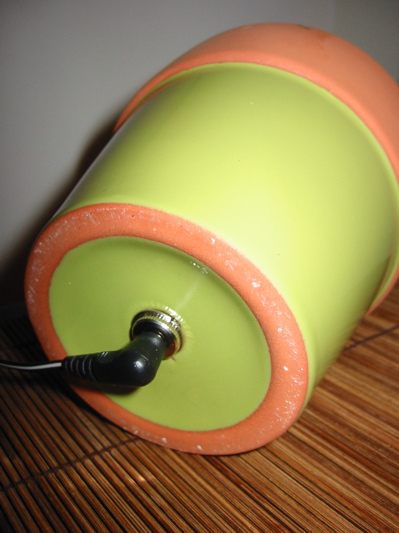
When I turned from using a 9V battery fueling the circuit to a wall wart, I had intended to drill a hole in the side of the pot near the bottom to pass the power cable through. After a couple of attempts, the near hideous scratching of the pot’s green glaze and a paralyzing fear of causing it to shatter I decided to use the pot’s drain hole as mother natured intended. Its hole-ness beckoned to me. Besides the socket I had fit almost perfectly. Unfortunately the pot can’t rest on its base anymore; it requires I use a stand as you see in the first picture. The current stand is a opened leatherman knock-off because it was the first thing I had on hand that fit the bill. It was a poor knock-off so it makes a better stand anyway.
Since pictures don’t show off its glow-y goodness, here’s a video I took of it doing its thing (in the dark so you can see it better):
So where did I get the idea to do this? I was playing around with the circuit on a breadboard and a little garden of LEDs glowing and fading in and out when the wife came by and said “Ooooo! Mushrooms!”. The idea for the finished product was a short hop away from there.


